|
|

|

|
|
|

|
|
|
|

|
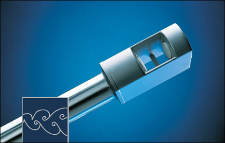
Derived from the Karman phenomenon of vortex shedding, the principle of measurement is based on vortices being shed when a flowing medium reaches a rod-shaped obstruction, whereby the vortex shedding frequency is a dimension for the flow velocity.
The flow vortices are ultrasonically scanned. In this way, compared to other scanning methods, flow velocities of as little as 0.5 m/s can be measured coupled with turndown ratios of 1 : 160. The vortices modulate the ultrasonic beam between an ultrasonic transmitter and receiver. The vortex frequency results from the demodulation.
A crucial advantage of the principle of measurement lies in the independence of density, pressure and temperature from the working medium. |

|

|

|
|

|
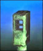
Vortex flow sensors VA have no moving parts, have outstanding fatigue strength even in rough conditions, excellent repeatability, long-term stability and are overload-proof. Measuring is practically inertia-free. The length of cable between sensor and evaluation unit can measure up to several hundred meters.
Solids are of no impairment as long as abrasion does not occur. In comparison to the vane wheel flow sensors, vortex flow sensors can be used for measuring in gases with considerably intensive solids content, without impairing the fatigue strength.
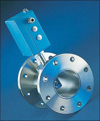
The pictured sensor with salt deposits was installed in a mine for several weeks. The slight deposits on the strut can easily be seen. In soiled condition drifts of max. +/-0.3 m/s result for velocities of up to approx.
12 m/s. |
 
|

|

|
A combination of vortex flow sensor VA and a suitable evaluation unit is necessary for successful measuring. |

|
|
|
|

|
Vortex flow sensors VA
Insertion probes for measurement of flow |

|

|
|
|
|

|
Vortex flow sensors VAT
Insertion probes for combined measurement of flow and temperature |

|
|
|

|
|

|
Vortex flow sensors VAR |

|
Twin vortex flow sensor for measuring the flow velocity and the ��
direction of flow, for example in traffic tunnels |

|
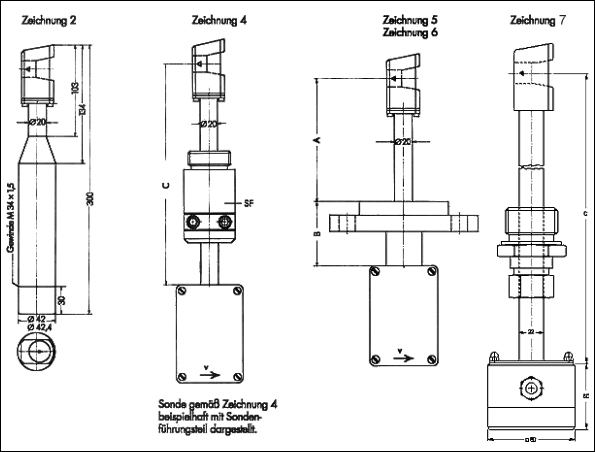
Designs of vortex flow sensors VA40 |

|
|

|
|
|
|

|
Drawing ZG2: extendable probe with probe tube diameter of 42 mm for greater insertion depths |

|
|
|
|

|
Drawing ZG4: probe with probe tube diameter of 20 mm, with sliding probe guide piece
for installation in pipelines/ducts |
|

|
|
|
|

|
Drawing ZG5: probe with probe tube diameter of 20 mm, with lapped flange and welded, integral flange
for making contact with the medium |

|

|
|
|
|

|
Drawing ZG6: probe as drawing 5, with EEx ia IIC T6 type of protection for use in zone 0 |

|
|
|
|

|
Drawing ZG7: probe with probe tube diameter of 20mm with sliding probe guide piece for installation in pipelines/ducts;
probes with an installation length of 500 mm or 1000 mm, probe materia stainless steel for use in non-hazardous areas |

|
Types of vortex flow sensors VA |

|

|
|
|

|
initial smallest measurable value approx. 0.5 m/s |
|

|
|
|

|
terminal measurable value: 40 m/s; 60 m/s and 80 m/s |
|

|
|
|

|
working temperature range: -20 ��C...+100 ��C; +180 ��C; +240 ��C |
|

|
|
|

|
maximum working pressure: 3 bar above atmospheric |
|

|
|
|

|
explosion-proof type of protection: EEx ia IIC T6 for zones 1 and 0 |
|

|
|
|

|
probe materials: stainless steel, titanium, tantalum and HASTELLOY |
|

|
|
|

|
necessary diameter of insertion opening: 40 mm |
Accessories for vortex flow sensors VA |

|

|
|
|

|
probe tubes of 350, 500 and 1000 mm length for screwing onto VA probes as in drawing 2 |
|

|
|
|

|
probe guide pieces with flange or screw thread connection, for installation of VA sensors in pipelines and ducts as in drawings 2 and 4 |

|
|

|
direction indicator for clamping onto the probe tube as in drawing 2,
may also be used as a depth indicator |

|

|
|
|
|

|

|
measured values from 0.7 m3/h and 0.4 m/s |
|

|
|
|

|
working temperature range �C10 ... 180 ��C |
|

|
|
|

|
maximum working pressure 10 bar / 1 MPa above atmospheric |
|

|
|
|

|
material stainless steel, titanium, Hastelloy |
|

|
|
|

|
measuring uncertainty < 1% of test value + 0.2 % full scale |
|

|
|
|

|
consistency +/- 0.2% |
|

|
|
|

|
available with integrated transducer |
|

|
|
|
Di |
Measuring range volume flow |
Measuring range flow velocity |
[mm] |
[m3/h] |
[m/s] |
25 |
0,7 ... 71 |
0,4 ... 40 |
40 |
1,8 ... 181 |
0,4 ... 40 |
50 |
2,8 ... 283 |
0,4 ... 40 |
80 |
7,2 ... 724 |
0,4 ... 40 |
100 |
11,3 ... 1131 |
0,4 ... 40 |
|
|
 
|

|


|
LDX1A ATEX |
|
|
|
|
|
|
|

|
isolation/supply unit for connection of vortex flow sensors VA in EEx ia IIC T6
type of protection |
|
|
|

|
|
|
|

|
|
|
|
|

|
power supply: 230 VAC, 24 VAC, DC supply with series connected DC/AC
converter possible! |
|
|
|

|
|
|
|

|
LDG16 miniature housing (W/H/D = 55/75/110) for 35 mm standard
assembly rails |
|
|
|

|
|
|
|

|
operation only permissible with non-Ex evaluation units: transducer U2a or
system instrument in LDG30 housing (see below) |
|
|
|

|
|
|
|

|
LDX1A ATEX and secondary evaluation unit are to be placed in a
non-hazardous space |

|
System instruments with display and keypad |
|
|
|

|
��P-Vortex
for connection of vortex flow sensors VA |

|
|
|

|
��P-Vortex-R
for connection of direction sensing
vortex flow sensors VAR |

|

|
|
|

|
VT-VA
for connection of vortex flow sensors VA and Pt100 temperature probes,
pressure as input value |

|

|
|
|

|
VP-VA
for connection of vortex flow sensors VA and absolute pressure gauges,
temperature as input value |

|

|
|
|

|
VTP-VA
for connection of vortex flow sensors VA, Pt100 temperature probes
and absolute pressure gauges |
|
|